Tools
Components
Instructions
This detector actually detects the absence of a bottle cap when a bottle passes a beam of light after leaving an automatic bottle filling machine. When one or more bottles without a cap are detected the filling machine is stopped by activating the emergency stop.
Introduction
When I got the question about detecting bottle caps it seemed quite simple at first: get a sensor to detect a metal object and you're done, right? Well, not really. So I started a conversation with the owner of Brewery Boelens to get the complete picture. Apparently the bottle caps that have to be pressed on the bottles are presented from a filler tube. Once in a while a cap does not exit that tube properly resulting in a bottle without a bottle cap. The next step in the filler station is printing the expiry date in the cap and with the cap missing that date is printed on the beer foam making the bottle unsalable. You wouldn't want a beer with some added ink solvents, would you?
Detecting a bottle cap can be done with an inductive sensor, so add a sensor and you are done, tright? No, not really. You have to detect the bottle too. So add a light gate and detect the bottle the moment the bottle passes the gate. Yeah, we are getting somewhere but it's not enough really.
I called the owner of the brewery and asked how his filling station worked. Apparently he used a PLC which has an emergency stop circuit. Opening that emergency stop circuit halts the filling station allowing the operator the fix the bottle cap filling tube.
Let's add a few requirements to make the detection workable:
- There must be a clear opening between two bottles so the light gate is closed between two bottles
- The inductive sensor triggers while the light gate is opened.
- The sensors are fast enough to trigger before the bottle has passed the gate.
- The code is never halted and continuously keeps listening for sensor inputs.
- A reset button is used to reset the alarm. To avoid accidental resets the button needs to be pressed for at least one second. The trigger is given when the button is released.
Flow description
Flow chart showing the loop logic
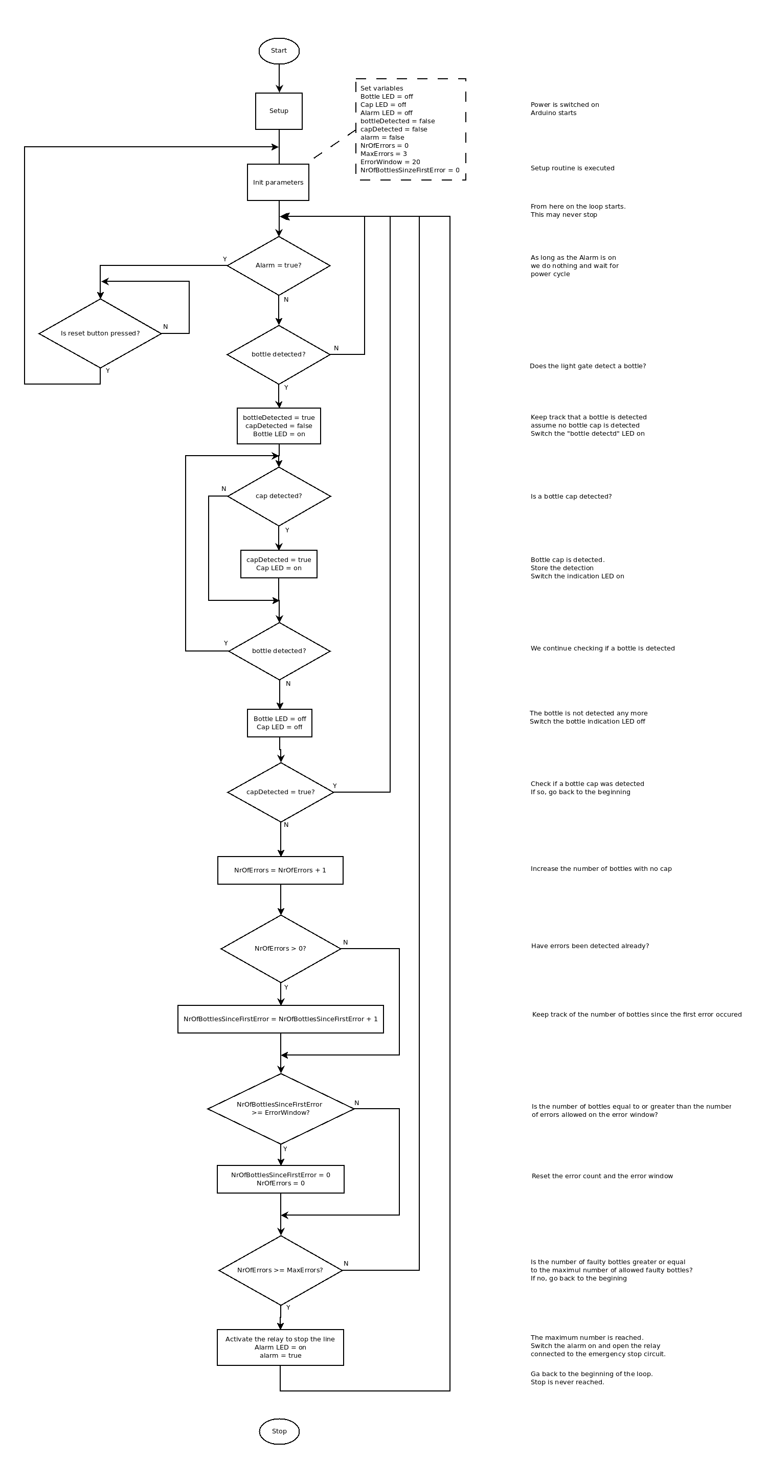
The flow chart on the left explains what the code needs to do. Creating such a flow chart makes coding a lot easier and avoids spaghetti code as it makes it necessary for you to think prior to start coding.
If you think you can simplify the process even further, please don't hesitate to let me know.
Hardware
Input
As stated in the introduction we will need three basic inputs
The light gate will detect the passing bottle and the inductive sensor will detect the bottle cap. I have created pages explaining the use of these sensors. Make sure to check these pages out before moving on. If you are not very experienced try out the different sensors individually before putting the whole bottle cap detector together
Output
Of course we need some form of output or our detector would be kind of useless. I like to use indicator LEDs if I don't have a display of some sort. So I added one for the detection of the bottle, one for the detection of the cap and one for when the alarm goes off. That last one is of course the most important one an d should not be omitted in your setup!
So here's the list of the outputs
- Bottle detected indicator LED
- Bottle cap detected indicator LED
- Alarm indicator LED
- Relay
Pinouts
As we now have a list of all the different connections we have to make we can decide what pins we are going to use on the Arduino. All inputs and outputs are digital without any need for Pulse Width Modulation.
Pin number | Direction | Description |
2 | Output | Bottle Detection indicator LED |
3 | Output | Cap detector indicator LED |
4 | Output | Alarm indicator LED |
5 | Input | Reset button |
6 | Input | Inductive sensor |
7 | Input | Retro-reflective light sensor |
8 | Output | Alarm relay |
Voltages and currents
The Inductive sensor and the light sensor require 24 volt while the Arduino, relay and the rest of the components run on 5 volt. As this project is to be installed in an industrial environment where 24 volt is a standard the higher voltage is easily covered. By using a buck converter we can convert this 24V to 5V efficiently. The question that remains is "How much current do we need at 5V?". So let's sum up the components that use 5V and the maximum current they need.
Name | Maximum current |
Arduino | 200mA |
Relay | 100mA |
LED | 20mA per LED |
Adding all this up we get a maximum current of about 360mA on the 5V line. This means that even a very small buck converter using a MP1584 chip can provide plenty of power. The buck converter linked in the component list above provides a maximum current of 3A.
So by getting the 24V from the industrial power and putting that through the buck converter we get the 5V. Of course it is very important to connect the 0V, also referred to as ground, of both voltages together. This is necessary to have a common voltage reference for both voltage potentials.
Schematic
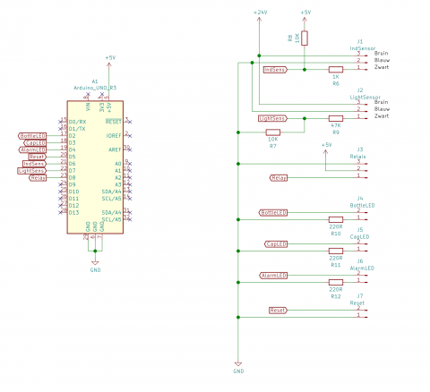
The schema is available in KiCAD format on the GitHub project page.
Building the prototype
Software
This project requires some experience with the Arduino framework. The code below contains plenty of comments so it is easy to follow.
DEBUG parameter
I like to be able to switch debugging voer the serial port on or off because sending data over the serial port if very time consuming. When running the code in production mode there generally is no serial port connected so there's no use in sending debug messages to the serial port. By defining a DEBUG parameter, setting it to true and encapsulating every Serial command in an if(DEBUG) {} command it is very easy to switch debugging on and off simply by setting the DEBUG parameter to true or false.
The code
#include "Arduino.h" #include "OneButton.h" //Define the used pins #define BOTTLE_DETECTION_LED_PIN 2 #define CAP_DETECTION_LED_PIN 3 #define ALARM_LED_PIN 4 #define RESET_BUTTON_PIN 5 #define INDUCTION_SENSOR_PIN 6 #define LIGHT_SENSOR_PIN 7 #define ALARM_RELAY_PIN 8 //The number of bottlkes without a cap within the error window that trigger a alamr #define MAX_ERRORS 3 //The number of bottles in the error window. The error window is opened when the first faulty bottle is detected. If the maximum number of faulty bottles is detected within this window the aram is triggered. #define ERROR_WINDOW 20 //Set the parameter below to true to get debug messages on the serial port //Set the parameter below to false to disable the serial port and not get any debug messages #define DEBUG false //Instaniate the varables int NrOfErrors; int NrOfBottlesSinceFirstError; bool bottleDetected; bool capDetected; bool alarm; bool buttonPressed; //Instantiate the button object and hook it up to the button pin/ OneButton button(RESET_BUTTON_PIN, true); //Create an array of LED statusses. This makes the code easier to read. enum ledStates { OFF, ON }; //Checks if a bottle is detected. //Returns false when no bottle is detected. //Returns true when a bottle is detected bool detectBottle() { if (digitalRead(LIGHT_SENSOR_PIN) == 1) { return true; } else { return false; } } //checks if a bottle cap is detected //Returns true of a bottle cap is detected //Returns false if no bottle cap is detected bool detectCap() { if (digitalRead(INDUCTION_SENSOR_PIN) == 0) { return true; } else { return false; } } //Switches the alarm relay on if the alarm state is ON void setAlarmRelay(ledStates state) { if (state == OFF) { digitalWrite(ALARM_RELAY_PIN, LOW); } else { digitalWrite(ALARM_RELAY_PIN, HIGH); } } //Switches on the LED that indicates if a bottle is detected when the bottle detected state is ON void setBottleLED(ledStates state) { if (state == OFF) { digitalWrite(BOTTLE_DETECTION_LED_PIN, LOW); } else { digitalWrite(BOTTLE_DETECTION_LED_PIN, HIGH); } } //Switches on the LED that indicates if a bottle cap is detected when the bottle cap detected state is ON void setCapLED(ledStates state) { if (state == OFF) { digitalWrite(CAP_DETECTION_LED_PIN, LOW); } else { digitalWrite(CAP_DETECTION_LED_PIN, HIGH); } } //Switches the alamr LED on indicating that an alarm is triggered void setAlarmLED(ledStates state) { if (state == OFF) { digitalWrite(ALARM_LED_PIN, LOW); } else { digitalWrite(ALARM_LED_PIN, HIGH); } } //This method is called when the button is pressed for at least 1 second void buttonLongPress() { //Set the flag indicating that the button has been pressed buttonPressed = true; } //Initialise the parameters used in the application void initParameters() { NrOfErrors = 0; NrOfBottlesSinceFirstError = 0; bottleDetected = false; capDetected = false; alarm = false; buttonPressed = false; //Initialise the indicator LEDs setBottleLED(OFF); setCapLED(OFF); setAlarmLED(OFF); setAlarmRelay(OFF); } //Set the hardware pin modes void setPinModes() { //Set the input pins pinMode(INDUCTION_SENSOR_PIN, INPUT); pinMode(LIGHT_SENSOR_PIN, INPUT); pinMode(RESET_BUTTON_PIN, INPUT_PULLUP); //Set the output pins pinMode(CAP_DETECTION_LED_PIN, OUTPUT); pinMode(BOTTLE_DETECTION_LED_PIN, OUTPUT); pinMode(ALARM_RELAY_PIN, OUTPUT); pinMode(ALARM_LED_PIN, OUTPUT); } //The set up routine is only called once when starting up the code. It's used to set everything up. void setup() { //Only set up the serial port when debug messages are used. if (DEBUG) Serial.begin(9600); //Connect the "long press" event to the buttnoLongPress method button.attachLongPressStart(buttonLongPress); //Set the hardware pin modes setPinModes(); //Initialise all parameters initParameters(); } //The loop method is called over and over again, thus providing the mail application functionality void loop() { //monitor de reset button button.tick(); //We can only start when there is no alarm if (!alarm) { //We wait for a bottle to be detected if (detectBottle()) { if (DEBUG) Serial.println("Bottle detected"); //Keep track of the fact a bottle is detected bottleDetected = true; //Suppose no bottle cap has been detected at this point capDetected = false; //Switch the "bottle detected" indicator LED on setBottleLED(ON); //We start the loop that runs as long as the bottle is detected and the reset button is not pressed while (detectBottle() && !buttonPressed) { //monitor the reset knop. We need this command here too, otherwise we can't get out of this loop button.tick(); //Check if a bottle cap is detected. Only take action the first time the cap is detecxted if (detectCap() && !capDetected) { if (DEBUG) Serial.println("Cap detected"); //Keep track that the cap is detected capDetected = true; //Swith the "bottle cap" indicator LED on setCapLED(ON); } } //The bottle has passed, switch the indicator LEDS off setCapLED(OFF); setBottleLED(OFF); //Take some action if no cap has been detected if (!capDetected) { //No cap detected, keep track of the count NrOfErrors++; if (DEBUG) { Serial.print("Number of faulty bottles = "); Serial.println(NrOfErrors); } } //If this is not the first error, increase the number of faulty bottles in the error window if (NrOfErrors > 0) { NrOfBottlesSinceFirstError++; if (DEBUG) { Serial.print("Number of bottles detected in the error window = "); Serial.println(NrOfBottlesSinceFirstError); } } //We check if the number of bottles is greater or equal to the maximum number of errors in the error window //If so, reset the error counts if (NrOfBottlesSinceFirstError >= ERROR_WINDOW) { NrOfErrors = 0; NrOfBottlesSinceFirstError = 0; } //If the maximum number of errors is reached at this point, this can only be within the fault window, so raise the alarm if (NrOfErrors >= MAX_ERRORS) { if (DEBUG) Serial.println("Maximum number of faulty bottles reached. ALARM!!"); //Keep track of the alarm alarm = true; //Switch the alarm indicator LED on setAlarmLED(ON); //Switch the alarm relay on setAlarmRelay(ON); } } } else { //Whe we get here, the alarm state is raised, so we wait for the reset button to be pressed. if (buttonPressed) { if (DEBUG) Serial.println("Reset button is pressed. Initialise parameters and start again."); //Reset is pressed, so we reset all parameters and start all over again. initParameters(); } } }
Result
Here's a video of the detector working at Brouwerij Boelens.