Tools
-
Wire cutter
A wire cutter is a special kind of pliers used to cut wires. Thicker wires are cut with a bevelled cutter. Thin wire and electronic wires are cut with a flush cut wire cutter.

-
Wire stripper
Wire strippers are pliers that are used to remove the plastic insulation from electrical wires. They exist in many different forms.
-
Glue
Glue is a chemical bonding agent between two items.

Components
Instructions
Check out the specs
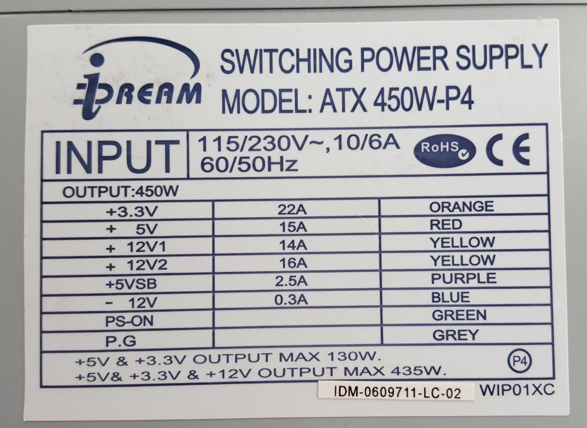
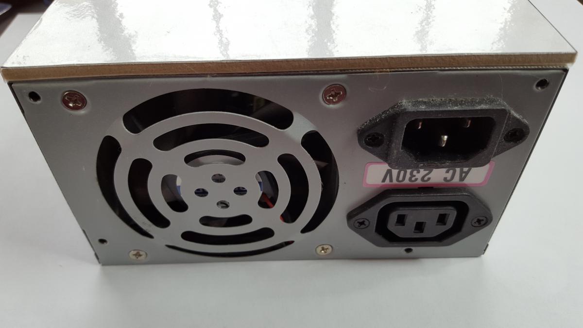
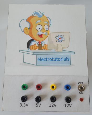
I selected a power supply from a pretty old PC. It has a maximum power of 450 Watt and enough different voltages for the projects I want to do. On newer versions you might find a 1.8V output. The maximum current that can be supplied on each line is pretty high. Do take that into consideration as we are not using a current limitation yet. On the other hand it will allow us to use the power supply for a vast variety of applications. For most if the projects we will do on this site you'll only need a couple of Amps max though. A power supply of 250 watt would have been enough. Plenty of very, very old computers are available. Check out junk yards, companies or schools in your neighborhood for broken or obsolete computers. Most of the times the power supply is still usable.
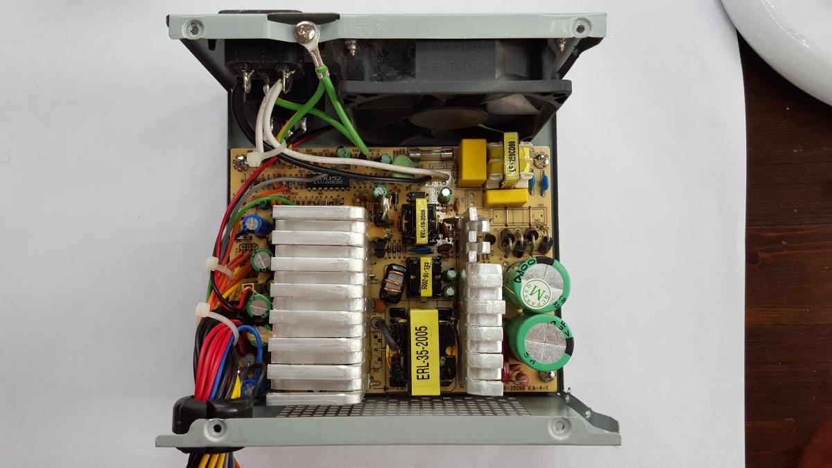
A look inside
For this project you do not need to open the power supply. Do not open it unless you know what you are doing! There are very high voltages used inside and even with the cable unplugged you can still get hurt!I am showing you the inside so you don't have to open it.You can see a lot of components, a ventilator and a bundle of wires. Those wires have different colors. The picture above about the specs shows you the voltages associated with those colors. These colors are standardized and will be the same on all computer power supplies.
Hook up the power switch
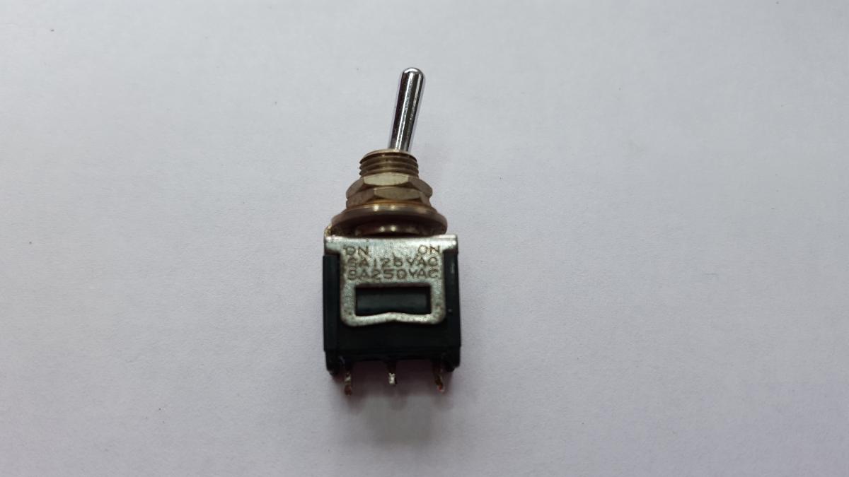
Now we need to get a regular, simple on-off switch. This switch just needs to connect the green wire to the black one when the power supply has to power up. In the off position this connection is broken. So even a switch with only two connections can be used. Use a multi meter if you are in doubt which connection are user in a certain switch position.
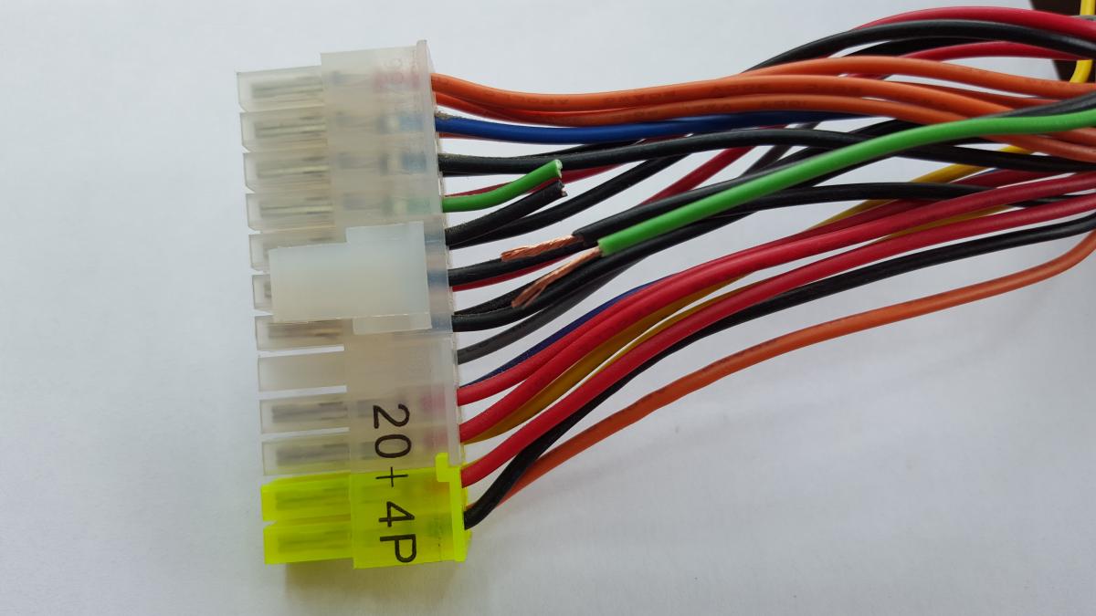
Computer power supplies will not work just like that even if they have a switch mounted on them. You still need to tell the power supply to power up. In a computer this is done by the power switch on the case. This switch connects the PS-ON line to ground. If you check out the biggest connector connected to the wires you will find a green wire at one side. Right next to it will be a black wire. Cut these off and strip the insulation back. Clear the wires from the bundle so they are completely free and can be handled separately.
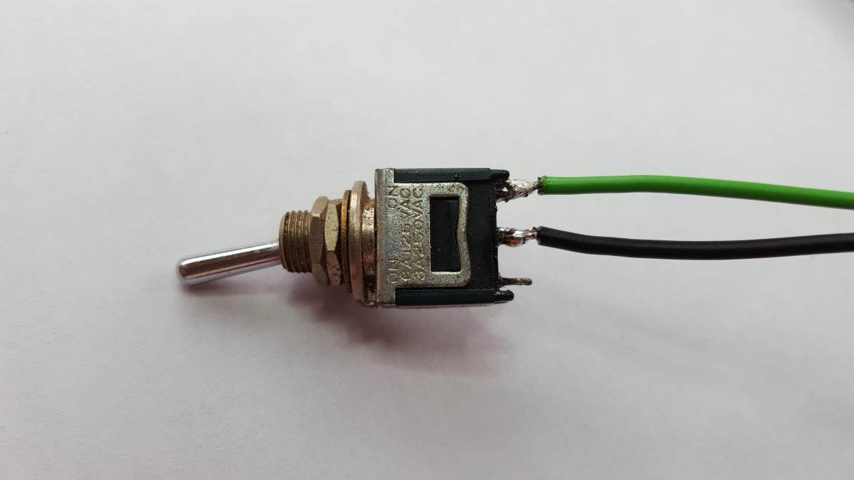
Now put some shrink tubing over the wires first and then solder the wires to the switch.
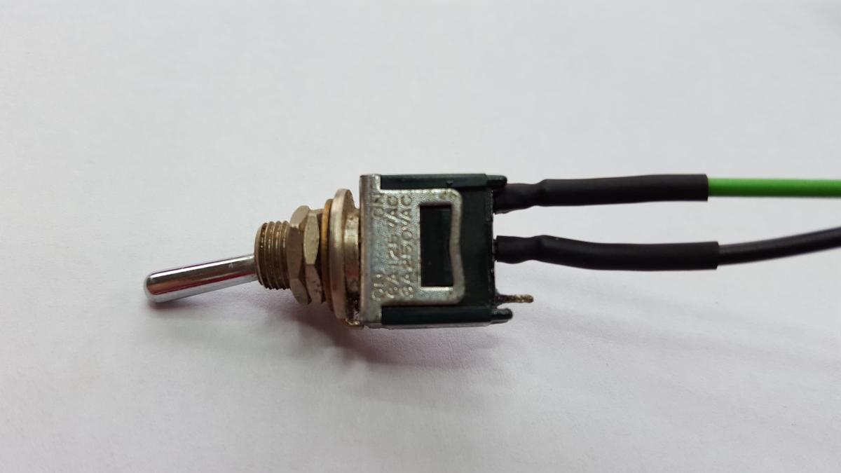
Slide the shrink tubing back over the wires and the connections and heat them up with a lighter, a hair dryer or a soldering iron. Be careful that the shrink tubings cover the connections completely and that you don't melt them. You certainly do not want to short these connections by accident as the power supply will then power up and might destroy anything hooked up to it.
The power good LED
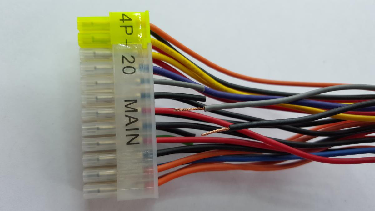
Now turn the big connector over and look for the gray wire. Right next to it you'll find a black wire. Cut these and strip the insulation back. Get these wires free from the bundle so you can handle them separately.
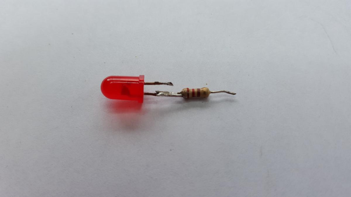
Now grab a regular red LED and a 220 Ohm resistor. Cut the leads of the LED and the LED short so you can solder them together. It does not really matter what side you solder the resistor to but I like to use the positive lead (the anode). On the LED that's the lead not at the flat side. If you have not cut the leads short yet, the positive lead is the longer one.Solder the 220 Ohm resistor to the positive lead and make sure the solder joint is solid.
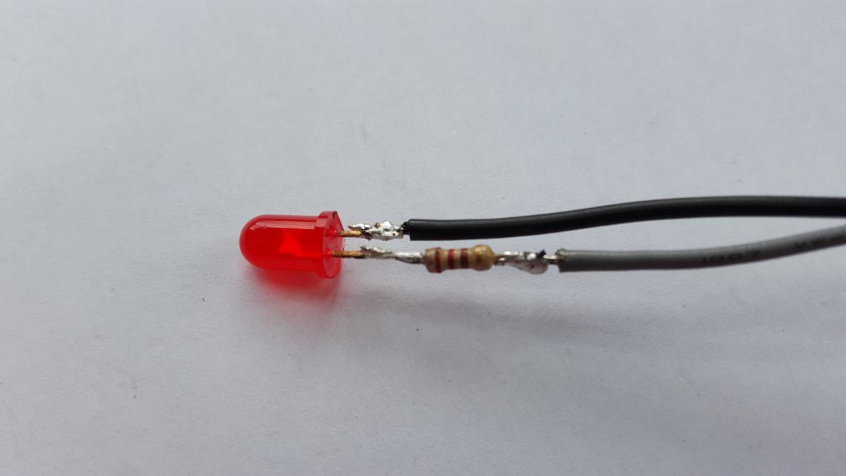
Slide bits of shrink tubing over the two wires and solder the gray wire to the resistor. Solder the black wire to the remaining lead of the LED.
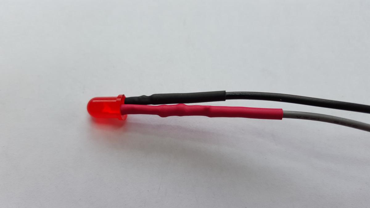
Slide the shrink tubings up to the LED and shrink the tubing.
Create the face plate
Measure the length and width of the top of your power supply. Mine is 140 by 150 millimeter. Open up your favorite vector drawing application and draw a rectangle in that size. I use the open source application InkScape . I added 60mm at the side where the wires exit. Within those 60mm I added two rows of 6mm circles. Each row has 5 circles. One for each voltage plus one for the switch and the LED. You can find the file I used below.
I then glued the paper on a piece of 3mm thick MDF wood, cut it out and drilled all the holes. I then covered the board with transparent sticky film. The result is not bad. I glued the board onto the power supply with hot glue.
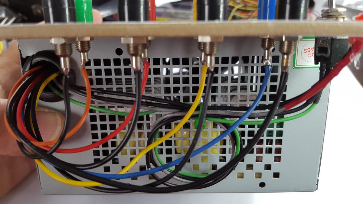
Soldering the banana sockets
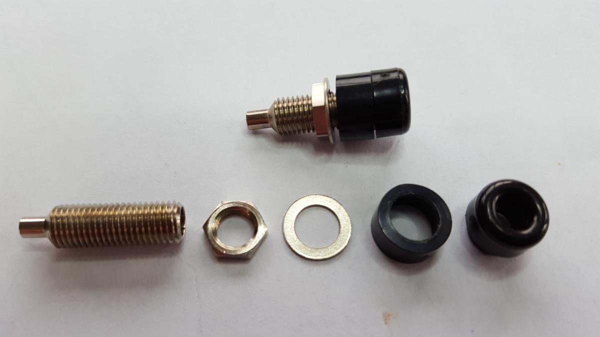
Take the banana sockets apart so you can solder the wires to them without having to worry about melting the plastic. It's also easier to clamp the sockets.
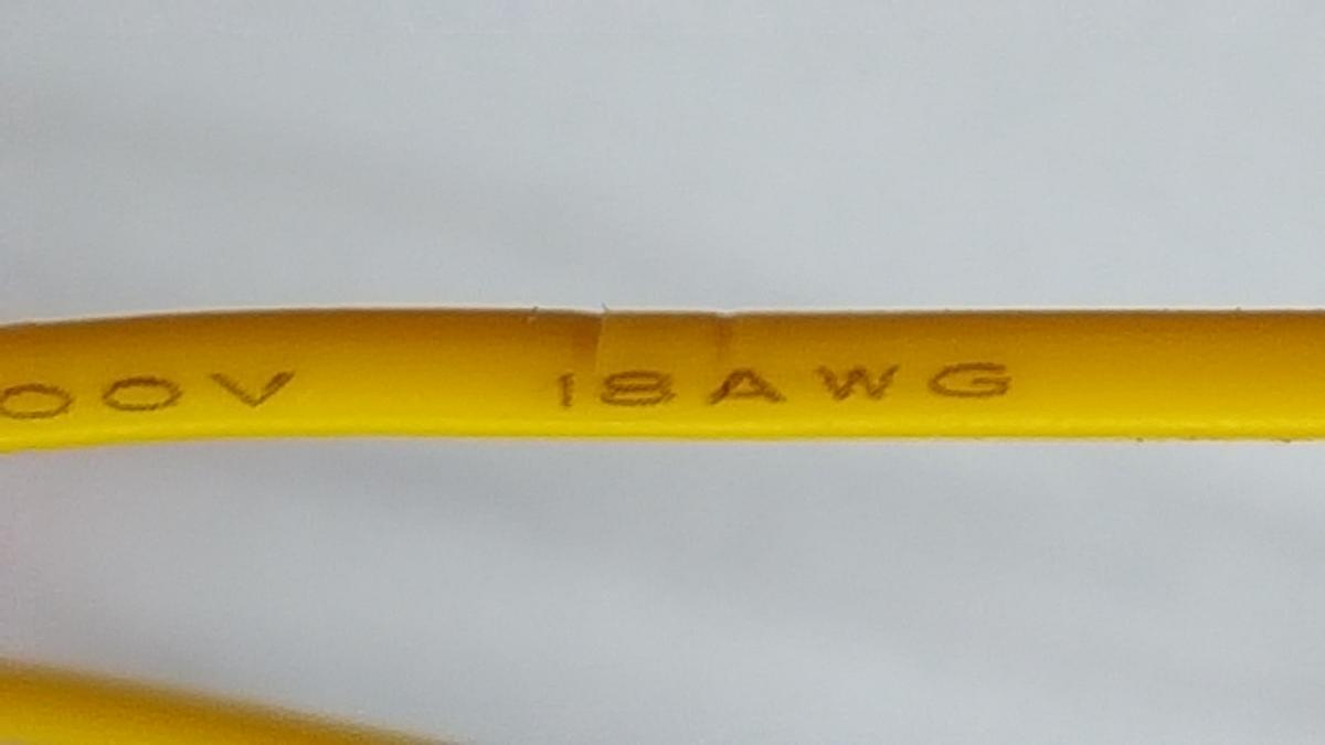
The top row of holes contains the connections to the different voltages. Take one cable from each needed color by using the table above. Cut these cables to the length needed so they reach the hole where the banana socket will be and add a few centimeters.The 12V wires are yellow. On my power supply I have yellow wires of two gauges, 18 and 20AWG. That's why the specifications give two different current values for the 12V line. The 18 AWG guage wire is the thickest, so we will use that one. All yellow wires are hooked up to the same connection inside the power supply. It's the thickness of the wire that's providing the limit.Do the same thing with the black ground wires. Make sure they are all of the correct length. You can use the colored wires as a guide.Cut off the wires you don't use close to the case. If you want to, you can tape them off or use a few bits of shrink tubing to protect them.
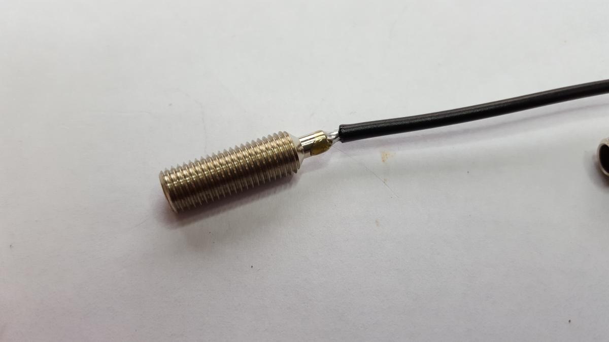
Strip back the wires and solder them to the banana sockets. Do this carefully.
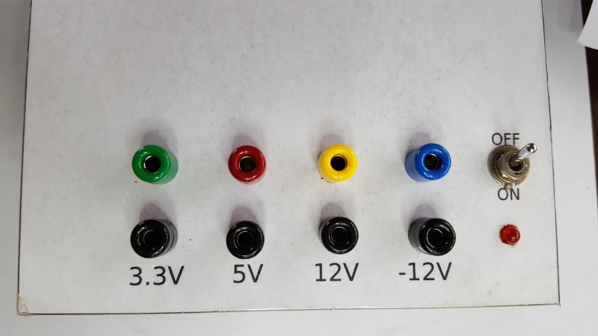
Put the nuts on the sockets, add the washer and put it though the hole from the bottom. Screw on the top, colored bits.Now mount the switch, making sure it's set up the correct way.Lastly fix the LED with some hot glue.
After some time the washers came loose which was very annoying. To avoid this from happening loosen the washers and apply some Threadlock or some super glue. Tighten the washers after the glue is applied.
Test
First of all verify that everything is hooked up correctly. Check every solder joint.
Hook up the power cable and switch on the power supply. The LED should light up. The ventilator will start spinning on most power supplies.Take your multi meter and measure the voltages of the outputs. Make sure they are all correct. You are now ready to power up your first project. Just take into account this power supply can deliver a lot of current and that can be detrimental to some devices.